IntroductionIntroduced in 1957, the IBM-made random access method of accounting and control (RAMAC) was the first disk drive. It consisted of 50 magnetic disks 24-inches in diameter and rotating at 1200 RPM (rotations per minute). Two air-bearing supported
magnetic heads accessed all 50 disks. The storage capacity of this system
was 5 MB with the data rate of 12.5 kB/s, and the system was rented
to the end user for $130 a month. The system used Aluminium sliders,
Mu-metal heads, had 20 tracks per inch and 0.002 Mb/in2, and the slider
/ disk spacing was about 20 micrometres (micro-metres = 20,000 nm).
The HDD is used by a computer to store the operating system (OS) and the user's data. Fierce competition between the drive manufacturers has pushed the cost of one MB of data to a very small amount of $1 to $2 per MB making a HDD of several GB in capacity relatively inexpensive and easily affordable by almost anyone. The HDD is one of the most important component of the modern PC: no application will run reasonably without the hard drive.
|
 |
<<
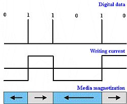
This figure illustrates a writing sequence
The drive channel electronics receive data in binary form from the computer and convert them into a current in the head coil. The current in the coil reverses at each 1 and remains the same at each 0. This
current interaction with the media results in magnetization of
the media, which direction depends on the current direction in
the coil. |
The reading process includes
excitation of the current in the head coil when the head "senses"
changes in the magnetic flux. The read voltage pulses at the flux transitions
are then translated into sequences of bits equal to 0 and 1. The so-called
Wallace's spacing loss factor postulates that the loss of magnetic signal
power will be proportional to the media - head separation. This requires
magnetic heads to fly as close to the disk surface as possible, which
forces modern heads to fly at a few nanometers only (compare this to
20,000 nanometers back in 1957!).
| Today's
magnetic head typically consists of an MR (magneto-resistive) or
GMR (giant MR) reading head and a thin-film inductive write head.
MR head design is based on the ability of metals to change their resistivity in the presence of a magnetic field. This effect was first found in 1857. The alloy of Ni and
Fe (81%/19%) is widely used in MR heads and is called Permalloy.
MR heads are suitable for extremely high bit density and have
superior signal-to-noise ratio when compared to inductive read
heads. Inductive thin film heads generate strong magnetic fields
at the gap between the poles, thereby magnetizing areas of the
media. |
 |
Continuous improvement of the head design allowed extremely high densities of magnetic recording with magnetic bits getting smaller and smaller. But, the head is only one component of the magnetic recording system, with magnetic media being extremely important as well.
The first magnetic media was called "particulate media" because it included particles of iron oxide (as the magnetic medium) and aluminum oxide (for abrasive resistance). Modern magnetic media is called "thin-film media" and consists of very thin layers with a total thickness of about 500 angstroms or 50 nm. The next figure presents a not-to-scale sketch of one of the kinds of thin-film media.
This thin sandwich is usually deposited by physical vapour deposition (when the atoms of different materials are formed on the surface with the minimum of chemical reaction involved) on the metal disk. Magnetic layer is needed to store the data. The reasons for having a thin carbon layer are simple: it increases mechanical durability of the disk and slows down corrosion of the magnetic layer. This carbon is sometimes called a diamond-like carbon (DLC) since it has similar chemistry to the diamond (both are mostly carbon), it is very hard (Diamond is VERY hard!), and it provides low friction. A thin layer of lubricant on the top is used to minimize the wear of the carbon layer. |
 |
Amazingly, year after year,
this super-thin structure gets thinner and thinner to keep the magnetic
head flying lower and lower to decrease that magnetic spacing loss...
Hard disk design
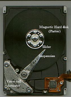
| Every hard
drive has one or many platters (which store magnetic data), usually
twice as many sliders with magnetic heads (to read and write data),
an actuator arm (to hold the suspension with the slider at the end),
and a voice-coil actuator (to move the actuator when the head is
accessing data). The drive is connected to the computer via the
interface connector.
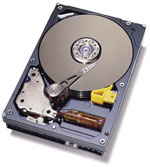
For some reason (unknown to us!), drive manufacturers always present their drives with the cover removed (see picture on the left). Since, the basic design of all the drives is quite similar, it is not clear exactly what they want us to see. The only important difference one can see from the picture of the opened drive is if its head is parked closer to the center of the disk (on the disk surface) or on the outer diameter of the disk (on a special ramp). This difference represents a major difference in drive design, ideology, and technology: the difference between contact start-stop drives (CSS) and load-unload (L/U) drives. Nowadays, the CSS design
can be found in drives for most Desktop computers, many of mobile
drives, and many of the drives for high-end servers. |
 |
L/U technology is gradually
displacing CSS in the mobile drives and servers. L/U design prevents
slider / disk contacts (except for the accidental ones) and increases
drive durability.
A dehumidifier bag in the
upper left corner serves the need to reduce humidity inside the drive.
High humidity enhances adhesion (stiction) between the sliders and the
platters. Sometimes the stiction becomes so high, that the drive spindle
is unable to rotate the drive without causing mechanical damage to the
suspension / slider system resulting in data loss. Another reason why
lower humidity is desirable is to reduce corrosion of the metal surfaces
inside the drive.
Now, lets take a look at the slider / disk interface of the modern drive.
In order to keep the magnetic head as close to the disk surface as possible, a self-pressurized air-bearing design is used for the sliders (see figure on the right).
| For the
CSS drives, the slider rests on the landing zone of the disk when
the power is off. When the drive is turned on, the disk starts spinning
and air pressure builds up between the slider and the disk. Eventually,
the slider starts flying at the altitude (called the flying height)
of a few dozen nanometers.
To get a feeling for what "a few nanometers" mean, lets remember that a human hair is about 30 microns in diameter (1 micron = 1,000 nm). An average bacteria can be typically a few hundred nanometers in size. Using some imagination,
the following example could be also used as an illustration: |
 |
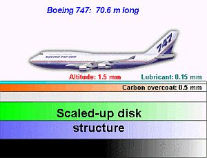 |
If the slider / disk
interface of the modern magnetic hard drive is scaled up to the
extent that the slider becomes as long as a Boeing 747 jumbo-jet
, then the following amazing picture (on the left) will appear:
Our slider-airplane
will fly at the altitude of only a few mm at the speed of approximately
65 mph periodically landing on its belly and taking off again
about 50,000 times. And still the surface of the runway, which
consists of a few mm-thick layers, will stay intact for years...
|
Basic hard disk drive concepts
| Track A concentric set of magnetic bits on the disk is called a track. Each track is divided into 512 bytes (usually) sectors. Sector Cylinder Data addressing |
 |
CHS addresses data by simply specifying the cylinder (radius), head (platter side), and sector (angular position). LBA assigns each sector of the drive a sequential number, which is simpler.
If you look into your BIOS, you will find listed the number of cylinders, heads, and sectors for each drive you have. Modern operating systems access data using LBA directly without the help of the BIOS. This reduces incompatibilities.
To improve performance and
increase data rate, HDDs utilize a small amount of fast solid-state
memory to store the most frequently used data. This memory is called
'cache' or 'buffer'. There are two types of cache memory organization:
look-ahead and write / read.
Hard disk formatting
Low level formatting
Formatting is the first step in making the drive ready for data storage
and retrieval. At this stage, the drive is being physically divided
into tracks and sectors. Low-level formatting stays unchanged for the
entire life of the drive unless the drive is re-formatted. Nowadays,
drives are usually sold with low level formatting already done.
Partitioning
Partitioning divides the drive into logical drives (C:, D:, E:, etc.).
Every drive has at least one "primary partition" (C:) and
may have many extended partitions. The primary partition contains drive
booting information in the Master Boot Record (MBR) and also keeps a
record of all other partitions. A partition is usually made using the
FDISK.exe program.
High-level formatting
High-level formatting prepares drive partitions for the operating system
by creating a root directory, from which all other subdirectories could
be created, and creating a File Allocation Table (FAT), which keeps
track of all information on the disks and all the relationships between
different pieces of information. A loss of the FAT translates into loss
of data, since the system will not be able to attribute data to specific
files even if the data themselves are intact. This operation is usually
done using the FORMAT.exe program.
The Hard Disk file system
The file system is a high-level
environment allowing the user to interact with the data stored in files
on various storage systems. It allows the user to actually address data
as files by keeping track of the file location, name, length, etc.
There are three primary file systems on today's IBM-based PC:
- FAT16 (Dos and Windows 3.x)
- FAT32 (Windows 95 and higher)
- NTFS (Windows NT and higher)
The main problem with FAT 16 is that it is unable to address more than 2.1 GB of data on each logical drive of the hard disk - a small number by today's standards. This means that if you use the FAT16 file system with a larger drive, you will be forced to partition it with the FDISK program to logical disks of not larger than 2 GB. Otherwise, you will lose some of drive's capacity. This is getting harder to do with modern disk drives of 20 GB and more in capacity. Another problem is with the way FAT16 divides sectors into clusters: the cluster size is only 2 KB for logical disks less than 128 MB and 32 KB when the disk size exceeds 1 GB. This means that the system will allocate 32 KB for even the smallest files of 1 KB.
There is no problem with addressing data with the FAT32 and NTFS systems. Problems won't appear until about 4 TB. The minimum cluster size for FAT32 is reduced to 16 KB. The main problem here is that the FAT32 and NTFS systems cannot read each other's disk partitions, which requires reformatting (FDISK and FORMAT) the drive when the system is changed.
Note:
Windows 98 allows changing older, FAT16 file system to newer 32-bit
FAT32 using a built-in program Drive Converter (FAT32), which can be
found in START --> PROGRAMS --> ACCESSORIES --> SYSTEM TOOLS
--> Drive Converter (FAT32).